- ARP (Address Resolution Protocol) is used to map IP addresses to MAC addresses by querying the MAC address corresponding to a target IP address.
- In network communications, data packets between hosts need to be encapsulated according to the OSI model from top to bottom before being sent out. Therefore, in LAN communications, both source/destination IP addresses and MAC addresses need to be encapsulated.
- Generally, upper-layer applications care more about IP addresses than MAC addresses, so the ARP protocol is needed to discover the destination host’s MAC address to complete data encapsulation.
Q&A
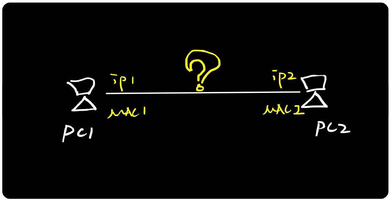
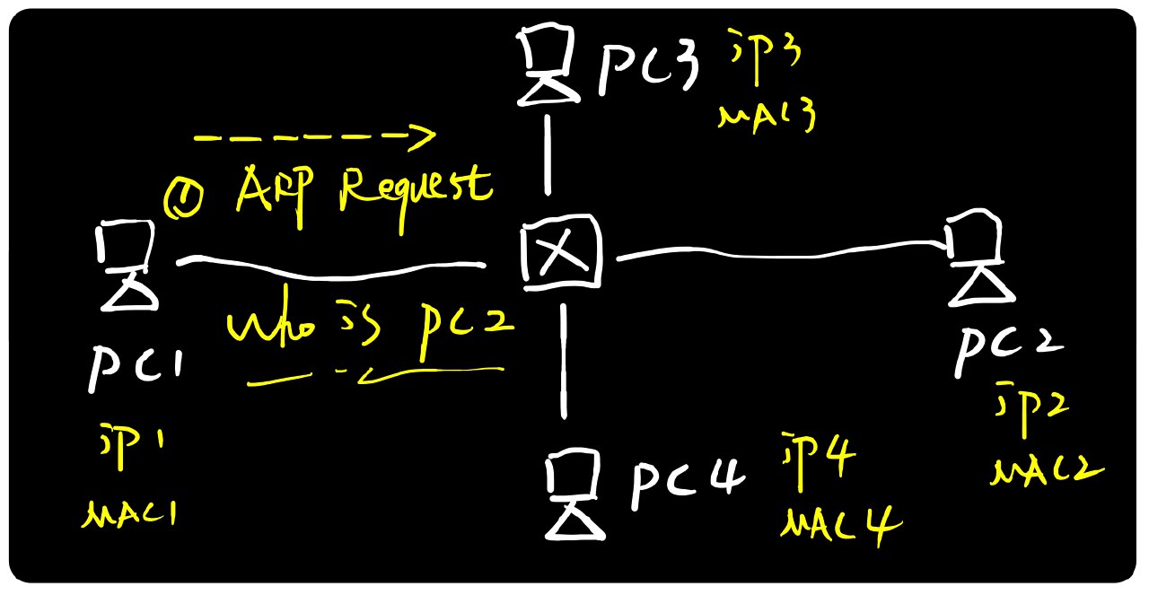
In the same LAN, how does PC1 handle communication when it needs to communicate with PC2?
According to the OSI data encapsulation sequence, the sender encapsulates data from top to bottom (from application layer to physical layer) before sending it out. Let’s use the process of PC1 pinging PC2 as an example:
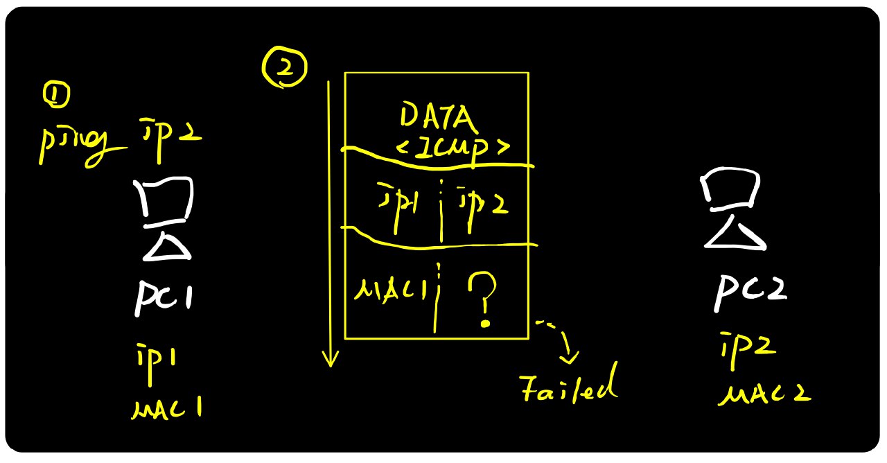
When PC1 encapsulates and sends data, we see a “failed” status in the above image. Why did the data encapsulation fail?
When we command PC1 to ping IP2, PC1 has the source and destination IP addresses needed for communication, but it lacks the destination MAC address. This is similar to sending a package with only the recipient’s name (IP) but no address (MAC) - the package can’t be delivered because the information is incomplete. So how do we obtain PC2’s MAC address?
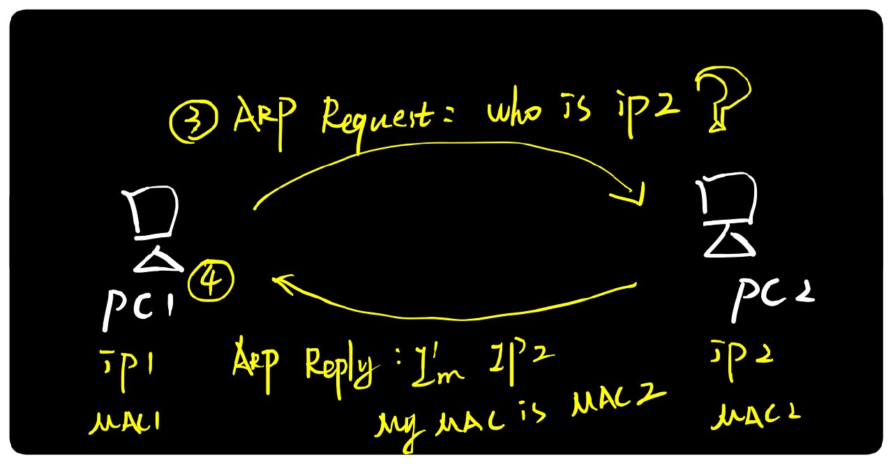
PC1 and PC2 undergo an ARP request and reply process. Through this interaction, PC1 obtains PC2’s MAC address information. Before actual communication begins, PC1 stores PC2’s MAC information in its local [ARP cache table], which contains IP-to-MAC address mappings, such as IP2<->MAC2. Then, PC1 can proceed with data encapsulation and begin the PING communication:
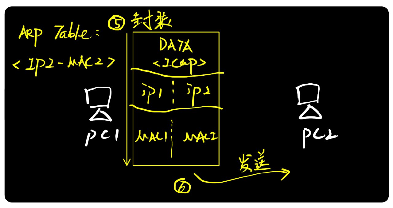
The ARP cache table has a time limit and is cleared when the device restarts. This means that future communications may require new ARP requests. On Windows/macOS systems, you can view this information using the command line
arp -a.
Broadcast Request, Unicast Response
In real networks, a LAN might have dozens or hundreds of hosts:
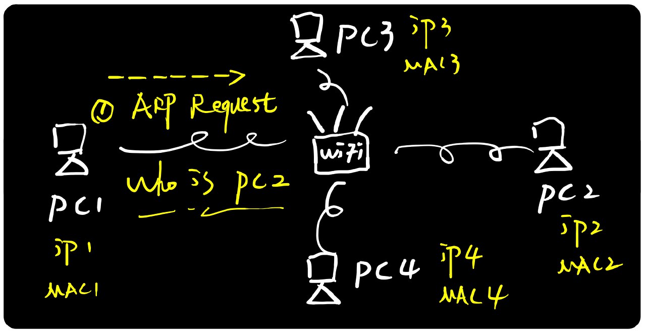
The ARP protocol utilizes Ethernet’s “broadcast” functionality: sending request packets in broadcast form. When switches or WiFi devices (wireless routers) receive broadcast packets, they forward this data to all other hosts in the same local network.
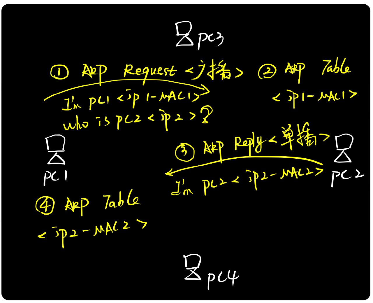
PC1’s broadcast request packet is received by all other hosts. PC3 and PC4 discard it (finding it’s not for them). PC2, upon receiving it, recognizes its own IP address in the request and doesn’t discard it, instead sending back an ARP response packet.
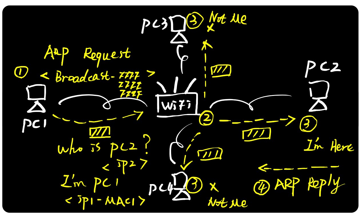
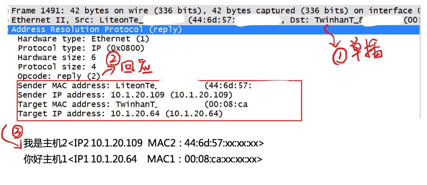
While ARP requests are broadcast, does PC2 need to broadcast its ARP response? The answer is no. Most network protocols are designed to be extremely efficient - unnecessary interactions are eliminated, information is consolidated where possible, and unicast is preferred over broadcast to maximize bandwidth and network speed. The complete information in an ARP request is: “My IP address is IP1, MAC address is MAC1, who is PC2, what is the MAC address for your IP2?” In other words, the ARP request first includes a “self-introduction” before the query. Therefore, when PC2 receives the request, it can store PC1’s IP and MAC mapping in its local [ARP cache table]. Knowing PC1’s location, it can return a unicast ARP response packet.
ARP Packets
ARP Request Packet
ARP Response Packet
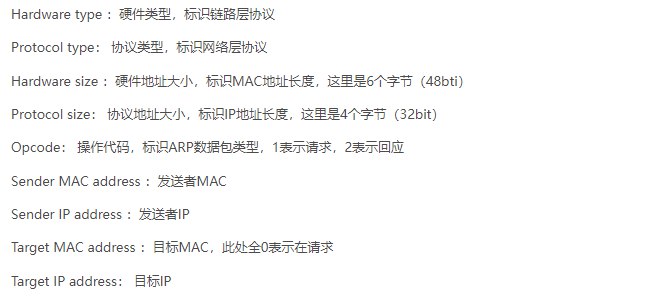
ARP Protocol Field Interpretation
Functionally, ARP protocol ultimately obtains MAC information, serving the link layer, making ARP a link layer protocol;
Structurally, both ARP and IP protocols are based on the Ethernet protocol, with their own Type values in the Ethernet protocol - 0x0806 for ARP and 0x0800 for IP, placing ARP at the network layer.
ARP resolves IP-to-hardware address mapping issues for hosts or routers within the same local network. If the target device and source host are not in the same local network:
<1> Host A cannot resolve Host B’s hardware address (and actually doesn’t need to know the remote host B’s hardware address);
<2> Host A needs to resolve Router R1’s IP address and send the IP datagram to Router R1;
<3> R1 finds the next-hop Router R2 from its routing table and uses ARP to resolve R2’s hardware address. The IP datagram is then forwarded to Router R2 using R2’s hardware address;
<4> When Router R2 forwards this IP datagram, it uses a similar method to resolve the destination Host B’s hardware address, ultimately delivering the IP datagram to Host B.
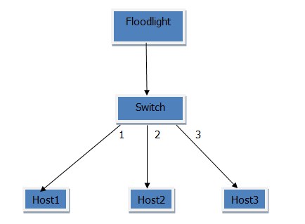
- Initially, h2 determines through AND operation with its own and h3’s IP addresses and subnet mask that they are in the same network segment and can communicate directly;
- When h2 performs layer 2 encapsulation of the data packet, it realizes it doesn’t know h3’s MAC address, so it sends an ARP broadcast packet;
- When the switch receives the ARP broadcast packet, having no flow table, it sends a packet_in message to the controller;
- Upon receiving packet_in, the controller sends packet_out to the switch and pushes flow table entries telling it to send the packet from all ports except port 2;
- When h3 receives the ARP packet, it adds its own MAC address to the packet;
- When the switch receives h3’s ARP packet, having no flow table entry, it sends a packet_in message to the controller;
- The controller learns h3’s MAC and IP addresses, sends packet_out to the switch, and pushes flow table entries for h3 to h2;
- h2 now knows h3’s MAC address, completes ICMP packet encapsulation, and sends the packet to h3;
- Since the switch has no flow table entry for h2->h3, it still sends packet_in to the controller;
- The controller sends packet_out to the switch and pushes h2->h3 flow table entries; now h2 and h3 can communicate directly through the switch without the controller!
Validity Check
Invalid cases: Source IP address is all 0s or is broadcast/multicast; Source MAC address is all 0s or is a multicast address.
Multicast MAC Address Detection
In the 48-bit MAC address defined by Ethernet, if the lowest bit of the first byte is ‘1’, it represents a multicast MAC address.
1if (mac[0] & 0x01) == 0x1 {
2		return true
3}